

Description
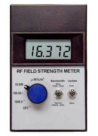
Technically a “power density” meter, the RF Field Strength Meter detects the electric field of radio and microwaves (RF) from .5 MHz to 3 GHz, and expresses the field strength as power density (.001 to 2000 microwatts/cm2).
This is an extremely sensitive meter which can accurately measure RF background even in rural areas far from any transmitters. The meter reads true power density directly on the display. Unlike other low-cost field strength meters, this meter’s frequency response does not depend on the characteristics of an external antenna; the internal detection system yields a flat response over a very wide range of frequencies.
Accuracy in the FM, TV and cell tower frequency range (30 MHz – 2.4 GHz) is +/-25%. Sensitivity is low by 50% (-3 dB) at the frequency limits .5 MHz and 3 GHz. (Sensitivity is 25% at 5 GHz. That is, you must multiply the reading by 4 when measuring microwaves at that high a frequency. At 10 GHz, sensitivity is about 10%.)
A High-Pass selector switch allows you to measure either the full bandwidth (“Wide” = 0.5 MHz – 3 GHz) or to apply a high-pass filter (“Narrow” = 6 dB/ octive rolloff with a knee at 100 MHz) that effectively allows only 100 MHz to 3 GHz through. In practice, this high-pass selector function can be used to estimate one additional parameter: the average frequency of the RF (if it is in the range 10 MHz – 500 MHz).
The RF Field Strength Meter is directional and it detects only the component of the electric field which has the same polarization as the long axis of the meter. That is, if only a vertically-polarized RF wave is present, but you turn the meter in the horizontal direction, it will essentially read zero. If you subsequently rotate the meter to vertical, it will then read the full power density of the RF wave. Most RF radiation has only vertical electric field, so the full strength can be read by holding the meter vertically. (At the end of this page is more information on how to read radio waves with other polarizations).
The meter has a 4 ½ digit display which reads in three ranges: .001 to 19.999, .01 to 199.99, and .1 to 1999.9 microwatts/cm2. For comparison, a low power 100 milliwatt dipole transmitter (typical 49 MHz cordless phone) produces about .010 microwatts/cm2 at a distance of 50 feet. This is 10x the minimum sensitivity of the meter. A FAST/SLOW update switch is normally set in the FAST position so you can quickly measure changes in the RF level. However, if the field strength is fluctuating rapidly, this switch can be set to the SLOW position, which averages the reading over several seconds.
The “zero” level will shift slightly with temperature. This shift is no more than +/- .010 microwatts/cm2 over the meter’s operating temperature range of 30° F to 110° F (-1 to 43° C). Two controls on the right side of the meter correct for this: a button, when pressed, turns off the pre-amplifier, so it is the equivalent of zero field. Then an offset control is rotated until the meter reads zero in the most sensitive “19.999” setting. After one minute or more of warm-up, this should be adjusted. Once adjusted, this need not be readjusted unless the temperature changes by more than 5° F. (Then a shift of about .001microwatt /cm2 will occur).
The RF Field Strength Meter comes with a standard 9-volt battery. A low-battery indicator shows on the display when approximately 10 minutes of battery life remain. Electric current consumption from the battery is about 15 ma, with low battery indication at about 7.6 volts.
[The following goes into more detail about using the meter to estimate the average frequency of an RF signal, and also the directionality of RF measurements.]
When measuring an RF signal of unknown frequency, you may notice that the reading is different when the Bandwidth switch is set to “Wide” vs. “Narrow”. If so, you can estimate the average frequency (averaged over the power density) of the RF spectrum. If it’s just a wave of a single frequency, you can estimate the frequency of that wave.
This estimate is done by measuring the power density with the Bandwidth switch set at “Wide”, and then measuring the power density with the switch set to “Narrow”. If these numbers are the same, the average frequency is above 500 MHz. If the “Narrow” number is less than 1% of the “Wide” number, then the average frequency is below 10 MHz. If the “Narrow” number is between about 1% and 96% of the “Wide” number, you can estimate average frequency from the ratio of the two numbers. (A written table is in the instructions).
Although most commercial RF transmitters radiate with a vertical antenna and thus a vertical electric field (so you can hold the meter vertically to measure the full power density), some RF radiation also has some horizontal component, due to reflections or transmitters that have antennas not pointed vertical. If you know where the transmitter is, you will only have to perform two readings to find the transmitter’s total power density at your position. These correspond to “Z” (vertical) and “X” (horizontal, but perpendicular to the direction of the transmitter). In theory, if you point the meter’s long axis toward the antenna (the “Y” direction), you will not detect any radiation from that antenna. This seems counterintuitive. (In fact, there may be some diagonal reflectors near you that produce a small “Y” component coming from the transmitter, but this is not usually significant).
In practice, if the back face of the meter is facing the RF source, and the meter is read first in the vertical orientation and then it is read after being rotated 90° to the horizontal position (with the back face still facing the RF source), the sum of those two numbers will be the true power density from that transmitter. (This addition is a “sum of squares”. That is, because power density is proportional to the square of the electric field, then the direct sum of these two numbers, and not the square root of the direct sum, will be the correct magnitude of the power density.) Most RF field sources are principally vertically polarized, in which case only the vertical reading needs to be done. To measure the full power density at a certain point in space, regardless of the sources’ locations, measure the vertical first (meter pointed upward). This will usually be the majority of the RF power density. Then make two measurements 90° apart, with the meter’s long axis pointed in the horizontal direction. For example, after the vertical measurement, measure holding the meter in a north-south orientation and then in an east-west orientation. The sum of these three numbers is the total power density at that point in space, regardless of the position of the transmitter or transmitters. An accuracy problem arises however, because your body can block RF radiation, so if an unseen transmitter is located on the opposite side of your body from the meter, the reading will be falsely low. If you hold the meter higher than your head, this problem disappears. The presence of your hand and arm will have some effect on the field strength at the meter, so the most accurate reading is taken by setting the meter on a non-metallic surface or using, for example, a plastic holder.