

Description
There is always a problem with ultra high resistance measurements: only a very small amount of current is flowing through the component that is being tested. Therefore certain precautions must be taken to prevent interference from external sources. A grounded conductive box with a copper mesh viewing screen allows testing of small components without interference from stray static electricity (usually caused by the operator’s movements). This box, which attaches to the meter, is included. In addition, the “sensitive” terminal (the terminal which is sensitive to static electric fields) can be connected through a shielded test cable (included) to measure any assembly that can’t fit in the conductive box.
The meter’s six resistance ranges are 19.999/ 199.99/1999.9 MegOhms and 19.999/199.99/1999.9 GigOhms. The highest direct resistance that can be read is 1999.9 GigOhms, and the minimum resolution is .001 MegOhm (1 KiloOhm), when the meter is set for reading 19.999 MegOhms. Overall accuracy is +/-2% of the reading, +/- one count.
In addition, there are two conductance (inverse of resistance) ranges. They are 19.999 NanoSiemens and 19.999 PicoSiemens. A NanoSiemen is 1 divided by a GigOhm. It’s the same as one NanoAmp per Volt. A PicoSiemen is one PicoAmp per Volt, or the inverse of one TeraOhm. Therefore, a 1 GigOhm resistor will have a conductance of 1 NanoSiemen, and a 1 TeraOhm will correspond to 1 PicoSiemen. Note that because one is the inverse of the other, then 2 TeraOhms corresponds to 0.5 PicoSiemen. The two conductance ranges therefore cover the following ranges of equivalent resistance: The first conductance range goes from .001 x 10-9Siemens (=1012 Ohms or 1 TeraOhm) to 19.999 x 10⁻⁹ Siemens (= about 5 x 10⁶ Ohms or 5 MegOhms), and the second conductance range goes from .001 x 10-12 Siemens (=1015 Ohms or 1000 TeraOhms) to 19.999 x 10⁻¹²Siemens (= about 5 x 10⁹ Ohms or 5 GigOhms). Accuracy is +/-2% of the reading, +/- one count, but external interference may cause additional inaccuracy.
It’s easier to measure very high resistances by using the conductance method than by using the standard resistance measurement method. With a standard resistance measurement, a certain pre-set amount of current is passed through the resistor that is being measured. For example, when the meter is set for 19.999 MegOhms, the internal circuitry causes exactly 100 NanoAmps (10-7 Amps) to flow through the resistor. A 10 MegOhm resistor would then have a voltage of 1 Volt (=107Ohms x 10-7 Amps) across it, and the display will read “10.000” as a result. When the meter is set to any of the 6 resistance ranges, the display reads proportional to whatever the voltage is across the test resistor. One volt always produces a half-full-scale reading, and 1.999 Volts always produces a full-scale reading of 19999, but the decimal point position depends on which scale is being used. There are 6 different pre-set amounts of current used: Starting with the 19.999 MegOhm and ending with the 1999.9 GigOhm range, the pre-set currents are 100,10, and 1 NanoAmp; and 100,10, and 1 PicoAmp. In each case, if the resistor voltage happens to be exactly 1.9999 Volts (when the appropriate amount of current is passing through it) the meter will show exactly full scale. When measuring conductance, a different technique is used: A voltage difference is applied across the resistor and then the current flowing through the resistor is measured. For purpose of illustration, think of the voltage as 1 Volt. Then the conductance (in Siemens) is the same number as the current (measured in Amps). For example, if a 10 GigOhm (1010 Ohms) resistor has 1 Volt applied across it, a current of 0.1 NanoAmp (10-10 Amp) will flow through the resistor, and this means its conductance is 10-10 Siemens or 0.1 NanoSiemen.
There are two major differences between resistance and conductance measurements:
1) A resistance measurement may take a very long time to settle to its final value if there is very much capacitance connected across the resistor; and 2) By the nature of an Ohm reading vs. 1/Ohms, if a very high resistance is being measured (a resistance which measures near full-scale on the meter), and the resistance is fluctuating by a factor of 10% from one second to the next (it may be noisy because a high resistance has a very “weak” signal), then the display will fluctuate 10% of 19999 counts, or about 2000 counts. This is very difficult to read. A low resistance (which is usually much less noisy) would show a very low number on an Ohm setting, so it would be much more stable. This means that when doing resistance measurements, small resistances are extremely stable, while large resistances are disproportionately unstable. However, if the meter is switched to conductance measurement, a high resistance will read a low number on conductance, and a 10% fluctuation may not even be visible as a one-count fluctuation.
Here’s an example of how capacitance can slow down the resistance reading: when measuring a 1 TeraOhm resistor, if less than 1 PicoFarad of capacitance is present, the resistance measurement will settle to within 2% of the final value in 4 seconds, and conductance measurement will settle in 3 seconds. However, if 10 PicoFarads is connected in parallel with the 1 TeraOhm, then resistance measurement requires 40 seconds to settle, while conductance still requires only 3 seconds. (Please note that these settling times apply to air-gap capacitance in the circuit. Solid capacitors often require a longer time to come to equilibrium, because they polarize slowly.) The slow settling of resistance measurements is because the tiny amount of current passed through the capacitor-resistor combination requires a long time to charge the capacitor up to its final voltage.
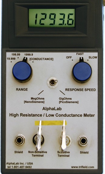
There are additional control knobs on the meter. The RESPONSE SPEED (signal averaging time) can be set to FAST (recommended) or SLOW (if the reading on FAST fluctuates too much). The previous quoted settling times were on FAST. There are two offset controls: 1) a zero-ohms offset (accessed through a small hole on the right side of the meter), which is adjusted to make the display read zero when the two test terminals are shorted. This zero can be done on any of the 6 resistance ranges and it does not need readjustment when switching to another resistance range. Readjustment is only needed if the temperature changes more than 30º F. 2) A zero-conductance offset (larger knob on right edge). This is adjusted to read zero when the terminals are not connected, and only when the RANGE knob is set on [CONDUCTANCE]. It must be readjusted when switching the toggle switch between [NanoSiemens] and [PicoSiemens]. This subtracts out the tiny currents (usually a few FemtoAmps) from the amplifier’s input, and from other mechanical effects that produce weak currents. This offset should be adjusted only after the other (small knob) offset is done, and should be adjusted more frequently than the small knob offset is adjusted.
Instructions
Calibration of zero-ohms.
The zero-ohms offset knob must first be set correctly. Plug the short alligator clips into the two terminals. The alligator clip with the larger diameter plug goes into the “Non-Sensitive Terminal”. To avoid electrostatic damage to the meter, it’s best to touch one of the two “shield” jacks before plugging in the “Sensitive Terminal”, and to do that anytime just before touching the “Sensitive Terminal”. Connect the alligator clips together by rotating them until they touch, and then clip one on the other. Turn the RANGE knob to any one of the numbers (but not to CONDUCTANCE), and the UPDATE SPEED knob to FAST (this will also turn the meter on). Note the knob sticking out of the right side of the meter. There is a hole in the case just next to that knob. Use a small screwdriver (included) to adjust the control at the bottom of the hole until the display reads zero. This adjustment will probably never need to be done again, but you should check once or twice a year to see if it really remains zero.
Resistance measurement.
Connect the unknown component (resistance) between the “Non-Sensitive” and “Sensitive” terminals, using the alligator clips. (If the component is small enough, you will not need to use the two cables; small components can be held directly over the meter by the alligator clips.) Snap the shielded box’s plug into either the left or right jack that says “shield”, making sure (by looking through the box’s screen) that none of the test assembly touches the inside of the shielded box. If the component is too big to fit inside the shielded box, use the two cables to extend the reach of the alligator clips. Note that the cable that fits the “Non-Sensitive Terminal” has only one conductor, whereas the “Sensitive Terminal” cable is coaxial (inner + outer conductors). If a long, unshielded wire were accidentally to be connected to the “Sensitive Terminal”, then the meter would fluctuate whenever the electric field in the room changes, even if that change is very small. If the electric field stops changing (either in strength or direction) for over 3 seconds, then the meter will become stable and it will read the correct amount. Because of this sensitivity to external fields, the “Sensitive Terminal” has a coaxial cable. The outer conductor shields the inner conductor. Note that anything connected (at the far end of the cable) to the terminal of this inner conductor should be shielded as much as possible from electric field in the room.
There are three separated voltage levels coming from the meter that should not be connected together, even though they all appear to be “case ground”: 1) The two banana connectors that say “shield” are true case ground. 2) The outer conductor of the Non-Sensitive Terminal” is almost at exactly the same voltage as the case ground, but an amplifier holds it near case ground voltage. The metal shaft of the “MegOhms”, “GigOhms” toggle switch is also at this potential. This is potential called the “guard ring”. 3) The “Non-Sensitive Terminal” is between zero and two Volts below case ground when measuring resistance. When measuring conductance, it is 3.5 Volts above the case ground. Never connect 1) to 2), 1) to 3), or 2) to 3).
To make a resistance measurement, switch the RANGE to 1999.9 and the toggle switch to GigOhms. If after a few seconds, the display fluctuates up and down significantly, switch the RESPONSE SPEED to SLOW. If the display instead shows a “1” on the far left side, it means the resistance is greater than 1999.9 GigOhms. (In that case, only the CONDUCTANCE will give a reading, as will be described later). However, if the display reads a number (1999.9 GigOhms or less), this is the correct resistance. If the number is very small (or zero), you may want to switch the RANGE knob from 1999.9 down to 199.99 or 19.999; if the number displayed is still small, switch the toggle switch from GigOhms down to MegOhms, and go through the 1999.9, 199.99, 19.999 ranges again until you see a large enough number to read with whatever level of resolution you need. If you go too far, a “1” will appear on the left side of the display, and no other digits will be displayed until you switch the range back again.
There may be several problems in getting a steady, precise number to be displayed. The first effect is 1) If a lot of capacitance is present (which is expected if you are measuring the resistance of a thin sheet of insulator that is sandwiched between the two electrode sheets), then the measured resistance may increase very slowly instead of immediately rising to the correct value. This problem with the resistance slowly rising (and taking a long time to become stable) is most likely to occur when on the highest resistance range: 1999.9 GigOhms. If the time required is unacceptably long, the CONDUCTANCE range will need to be used. Another effect 2) on stability of the displayed number may arise from external DC electric fields that are changing, while the test assembly is not properly shielded from these fields. ‘Proper shielding’ means that the assembly is surrounded by metal foil or metal screen which is itself connected to one of the meter’s two “shield” connectors. A third problem has to do with the components that are being tested. These may retain charge in certain regions, and these regions are usually slow to discharge. An example of this that was mentioned earlier is a real-world capacitor. For example, a 10 PicoFarad real-world capacitor charged to 1 Volt may be discharged through a 1 TeraOhm capacitor. This combination of resistor and capacitor should discharge to ½ of its previous value every 7 seconds. That is, after 7 seconds, the capacitor should retain ½ Volt; after 14 seconds, it should retain ¼ Volt, etc. At first, a real-world capacitor will act this way – cutting its voltage in half every 7 seconds. By the time the voltage is down to around 1/100 of a Volt, it may slow down, and cut its voltage in half every 15 seconds. Eventually it gets slower and slower, so that the last bit of charge takes an unexpectedly long time to remove. This will cause the meter display to take a very long time to settle to its final value. There may also be charged insulating surfaces on the components that are being tested. The slow discharge of these surfaces, even if the surfaces are not directly connected to the “Sensitive Terminal”, will cause a changing external field, which causes the display to read either too high or too low for a long interval of time before it finally settles. If an insulating surface of a ‘component that is being tested’ is accidentally rubbed, it may acquire static charge, and this problem (above) will result. Generally, any static electricity on the component can be removed before measurement is done, by using a neutral ionizer or by dipping the component in a (grounded) container of water and then shaking dry. The first effect, 1) (mentioned above), having to do with capacitance, can be overcome by using CONDUCTANCE. The second effect, 2) (also mentioned above), having to do with unexpectedly slow discharge of capacitance, in which the last little bit of charge is much slower to remove than it should be, cannot be overcome by using either resistance or conductance. If this second effect is a problem, try to reduce any ‘capacitance that involves solid insulators’ from the assembly you are measuring. Air-gap capacitance will not cause this second effect, so air-gap capacitance need not be eliminated. Another problem arises from measuring the resistance of ordinary materials that are not usually used to make resistors. With many types of material, the resistance depends on how much voltage is applied across the material. That is, a given sample may have 1 Volt across it when 1 NanoAmp is passing through it; but 2 Volts when 3 NanoAmps are passing through it. However, in an ideal resistor, if 1 Volt corresponds to 1 NanoAmp, then 2 Volts would correspond to 2 NanoAmps. Many materials will have a lower and lower resistance as you raise the voltage across the terminals.
Conductance Measurement.
If the resistance is higher than 1999.9 GigOhms, or if the capacitance of the circuit is so high that the resistance reading is drifting up too slowly to wait for it to stabilize, as in the first effect 1), use the conductance method of measurement. Switch the RANGE knob to [CONDUCTANCE]. There are two ranges of conductance: 19.999 NanoSiemens and 19.999 PicoSiemens. A Siemen is a measure of the amount of current (in Amps) that will flow through the component if 1 Volt is applied across it. A component with a conductance of .4 PicoSiemens means that .4 PicoAmp will flow through it if 1 Volt is applied across it. This component may therefore be called either one of the following: a 2.5 TeraOhm resistor or a .4 PicoSiemen conductor.
Before taking a reading, the ‘conductance offset’ must be adjusted correctly. This offset must be adjusted more frequently than the ‘zero-ohms offset’ that was previously adjusted. ‘Conductance offset’ is controlled by the knob sticking out of the right side of the meter. A circuit which has “zero conductance” is an open circuit. (This is in contrast to “zero resistance”, which is a short circuit.) Therefore, to zero the conductance, you must first disconnect the two test terminals (Sensitive and Non-Sensitive) from each other, and of course also disconnect (on at least one side) any component being tested. Leave the alligator clip (or coaxial cable) plugged into the “Sensitive Terminal”, but disconnect everything else from that Sensitive Terminal’s clip. If there is a component that is ready to test, one of its leads can remain connected to the “Non-Sensitive Terminal”. This will minimize the number of movements needed to connect the component for testing after a correct ‘zero conductance offset’ is done. Avoid touching or rubbing the plastic ring around the “Non-Sensitive Terminal”, or the plastic ring separating the inner from outer conductor on the “Sensitive Terminal”. Static charge could build up and it would require some time to dissipate.
Once the component is ready to test, but not yet connected to the “Sensitive Terminal”, plug the conductive box into its place, if possible. Switch the toggle switch to [PicoSiemens] (same position as GigOhms). Then rotate the conductance offset knob (sticking out of right face of meter) until the display reads near zero. This is the correct setting when the toggle is on [PicoSiemens], but the knob may need a different setting if the toggle is later set to [NanoSiemens] (re-zero the conductance offset whenever you change the toggle switch setting). Then remove the conductive box (if it’s used) and connect the component to test. Remember that in this conductance setting, a small number means high resistance, and a large number means low resistance. The conductance offset may shift by one count or more if the meter’s temperature changes by at least 2 degrees F. It may also shift by several counts if there is some charge on the surfaces of the test assembly; as this charge dissipates, the offset level shifts slightly. In the most sensitive toggle position (PicoSiemens), each Count represents a change of 1 FemtoAmp flowing through the component if 1 Volt is applied across that component. (In reality, 3.5 Volts is across the component, so each count on the display actually represents a current differential of 3.5 FemtoAmps.) Because a FemtoAmp (10-15 Amp) is so small, the assembly is very susceptible to external electric fields and to temperature changes which will affect the amplifier’s offset current. The conductive box should be used if possible. Again, avoid touching or rubbing any insulating surfaces when connecting the component to be measured. If the reading is initially unstable, check the shielding and/or stand very still to avoid movement in the room’s electric field.
SPECIFICATIONS
Measures resistance in 6 ranges from 19.999 MegOhms to 1999.9 GigOhm. Accuracy is +/-2% of the reading +/- 1 count. The 6 measurement currents are 100 NanoAmps down to 1 PicoAmp in factors of 10.
Measures conductance in 2 ranges: 19.999 NanoSiemens and 19.999 PicoSiemens. Accuracy is +/-2% of reading +/- 1 count. During conductance measurements, 3.5 Volts is applied across the component.
A “RESPONSE SPEED” control allows selection of either FAST meter update (1/3 second time constant), or SLOW (2 second).
Noise: for resistance greater than 10 GigOhms, RMS noise per 1/3 sec sample (FAST) is 0.0007 PicoSiemens. For less than 10 GigOhms, RMS noise per 1/3 sec sample is (10 GigOhms/R)1/2 x 0.0007 PicoSiemens. The noise per 2 sec sample (SLOW) is approximately half as much. The effect of this thermal noise on the displayed resistance can be calculated by first converting the expected resistance value to conductance (by inverting). Then add or subtract the conductance noise and convert back to resistance, These resulting “added” and “subtracted” numbers are the 70% confidence limits of the displayed resistances, ignoring outside interference.
Battery is a standard rectangular 9 Volt type, with “LOW BATTERY” appearing on the display when approximately one hour of battery life remains. Battery life is about 40 hours using an alkaline, and 25 hours using a regular battery. A battery is included.
Warranty for this meter is one year. Made by AlphaLab,Inc. (USA).